1. Gather Design Conditions
Example City, State: Anchorage Alaska
Source: ASHRAE
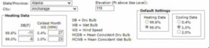
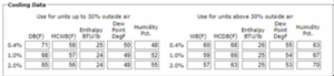

2. Gather Design Conditions – Cont’d
- Location: Anchorage, Alaska
- Design Temp: 70° F
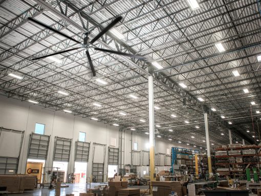
- Building Size: 300’L x 100’W x 25’H
- Garage Door: 8’W x 13’H
- Walls: Metal with 1‐inch blanket insulation
- Windows: None
- Doors: Metal‐ single sheet
- Roof: 1” Blanket Insulation under deck
- Floor: Non‐Insulated
- Air Changes: 2 per hour
- Design for 99.0% Heating Data
3. Type Selection
When selecting unit heaters consider the following: 1) type of heating medium available; gas, electricity, fuel oil, steam or hot water; 2) type of unit (Vertical, Horizontal or Power- Throw); 3) mounting height; 4) sound level; and 5) size. For some applications mounting height may narrow possible selection down to one or two models of particular type. However, the wide selection of Modine unit heaters makes it possible to meet most requirements.
Selection Tip:
If the building has a negative pressure, consider choosing a unit heater with separated combustion.
Steam/hot-water horizontal delivery unit heaters
A propeller fan moves room air through a condenser which is heated by steam or hot water. Adjustable louvers positioned horizontally in the air discharge opening permit heated air to be directed down, up, or straight out. Vertical louvers (optional) permit complete directional control of heated air. Steam and hot water unit heaters are also available in vertical air delivery models.
Gas-fired propeller or blower fan unit heaters
A propeller or blower fan is the air mover pushing room air through the heat exchanger. Horizontally positioned adjustable air deflectors permit heated air to be directed up, down, or straight out. Vertically positioned deflector blades (optional) may be added for complete directional control of heated air.
Oil-fired unit heaters
A motor-driven propeller fan directs room air over the exterior surfaces of the heat exchanger. When the burner is ignited a combination fan and limit control prevents fan operation until the heat exchanger has warmed up and after the burner is shut down; allows the fan to run until the heat exchanger has cooled. Horizontal and optional vertical louvers provide complete directional control of heated air.
Electric unit heaters
Vertical delivery unit heaters (illustrated) and horizontal delivery units are available. Finned tube heating elements located in the air stream heat the room air or drawn into the unit by the propeller fans. Horizontal delivery units are equipped with adjustable louver-type air deflectors. Vertical delivery models may be used with or without air deflector devices (optional). Three air deflector assemblies are offered, each with its own distinctive air distribution pattern, Heavy-duty, long heat throw, horizontal delivery models are also available.
Size Selection
Following “type” selection for each space, heater size must be chosen to offset the heat loss of the space, taking into account heat-throw or spread (in the case of verticals) and piping arrangement. To select size:
- Determine inside temperature to be maintained and design outside temperature for your locality. The difference between these two figures is the design temperature difference.
From Above Example:
- Design Temp: 70° F
- Winter OAT: -11° F
- Design Temp Difference = Design Temp – Winter OAT = 70 + 11 = 81 °F

- Calculate net areas in square feet of glass, wall, floor and roof exposed to outside temperature or to unheated spaces. Calculate doors as all glass.
| WALLS | LENGTH (FT) | HEIGHT (FT) | TOTAL SQ FT |
| NORTH | 300 | 25 | 7,500 |
| SOUTH | 300 | 25 | 7,500 |
| EAST | 100 | 25 | 2,500 |
| WEST | 100 | 25 | 2,500 |
| TOTAL GROSS SQ. FT | 20,000 |
| WINDOWS | QTY | LENGTH (FT) | HEIGHT (FT) | TOTAL SQ FT |
| NORTH | N/A | |||
| SOUTH | N/A | |||
| EAST | N/A | |||
| WEST | N/A | |||
| TOTAL SQ. FT | N/A |
| DOORS | QTY | LENGTH (FT) | HEIGHT (FT) | TOTAL SQ FT |
| NORTH | 1 | 8 | 13 | 104 |
| SOUTH | ||||
| EAST | ||||
| WEST | ||||
| TOTAL SQ. FT | 104 |
| ROOF | LENGTH (FT) | WIDTH (FT) | TOTAL SQ FT |
| 300 | 100 | 30,000 |
| FLOOR | NORTH | SOUTH | EAST | WEST | TOTAL |
| EXPOSED FLOOR | EXPOSED LENGTH (FT) | EXPOSED LENGTH (FT) | EXPOSED LENGTH (FT) | EXPOSED LENGTH (FT) | EXPOSED LENGTH (FT) |
| 300 | 300 | 100 | 100 | 800 | |
| PERIMETER | 800 |
| VOLUME | LENGTH (FT) | WIDTH (FT) | HEIGHT (FT) |
| 300 | 100 | 25 | |
| VOLUME (CU. FT) | 750,000 |
| TOTAL GROSS WALL AREA | 20,000 | SQ. FT |
| (MINUS) NET GLASS AREA | 0 | SQ. FT |
| (MINUS) NET DOOR AREA | 104 | SQ. FT |
| NET WALL AREA | 19,896 | SQ. FT |
2. Select heat transfer coefficients from table on next page (or the ASHRAE Handbook) and compute heat transmission loss for each type of area in BTU per hour by multiplying each area by its coefficient times the temperature difference. The overall coefficient of heat transfer is the U-factor. The steady state thermal resistance of something is known as its’ R-value. Heat loss calculations use the U-factor, however, the U-factor can be calculated if the R-value is known.
Common Heat Transfer Coefficients
| Building Material | “U” Factors | ||
| WALLS | |||
| Poured concrete, 80#/cu. ft. | |||
| 8-inch | 0.25 | ||
| 12-inch | 0.18 | ||
| Concrete block, hollow cinder aggregate | |||
| 8-inch | 0.39 | ||
| 12-inch | 0.36 | ||
| Gravel aggregate | |||
| 8-inch | 0.52 | ||
| 12-inch | 0.47 | ||
| Concrete block, w/4-inch facebrick | |||
| Gravel, 8-inch | 0.41 | ||
| Cinder, 8-inch | 0.33 | ||
| Metal | |||
| (un-insulated) | 1.17 | ||
| w/1-inch blanket insulation | 0.22 | ||
| w/3-inch blanket insulation | 0.08 | ||
| Frame | |||
| 2 X 4 w/1/2″ asphalt sheathing and
wood siding, 1/2″ gypsum wall board (un-insulated) |
0.23 | ||
| w/3″ insulation | 0.07 | ||
| ROOFING | |||
| Corrugated metal (un-insulated) | 1.50 | ||
| w/1″ bolt or blanket | 0.23 | ||
| w/1-1/2″ bolt or blanket | 0.16 | ||
| w/3″bolt or blanket | 0.08 | ||
| Flat metal | |||
| w/3/8″ built-up roofing | 0.90 | ||
| w/1″ blanket insulation under deck | 0.21 | ||
| w/2″ blanket insulation under deck | 0.12 | ||
| Wood/1″/
(un-insulated) w/3/8″ built-up roofing |
0.48 | ||
| w/1″ blanket insulation | 0.17 | ||
| Wood/2″/
(un-insulated) w/3/8″ built-up roofing |
0.32 | ||
| w/1″ blanket insulation | 0.15 | ||
| Concrete slab/2″/
(un-insulated) w/3/8″ built-up roofing |
0.30 | ||
| w/1″ insulation board | 0.16 | ||
| Concrete slab/3″/
(un-insulated) w/3/8″ built-up roofing |
0.23 | ||
| w/1″ insulation board | 0.14 | ||
| Gypsum slab/2″/
(un-insulated) w/1/2″ gypsum board |
0.36 | ||
| w/1″ insulation board | 0.20 | ||
| Gypsum slab/3″/
(un-insulated) w/1/2″ gypsum board |
0.30 | ||
| w/1″ insulation board | 0.18 | ||
| WINDOWS | Vertical, single-glass | 1.13 | |
| Vertical, double-glass, 3/16″ air space | 0.69 | ||
| Horizontal, single-glass (sky light) | 1.40 | ||
| DOORS | Metal–single sheet | 1.20 | |
| Wood, 1″ | 0.64 | ||
| Wood, 2″ | 0.43 | ||
| “F” Factors for Floor Heat Loss | “F” Factor |
| FLOOR | |
| Design Temps (i.e. Montreal – 16,
Milwaukee -6, St. Louis 7, Chattanooga 15) |
|
| -15F to -19F, no insulation | 50.00 |
| -15F to -19F, 24″ thick, R=3.75 insulation | 43.00 |
| -5F to -9F, no insulation | 50.00 |
| -5F to -9F, 24″ thick, R=3.75 insulation | 38.00 |
| 6F to 10F, no insulation | 50.00 |
| 6F to 10F, 18″ thick, R=3.75 insulation | 31.00 |
| 11F to 15F, no insulation | 50.00 |
| 11F to 15F, 12″ thick, R=3.75 insulation | 31.00 |
| NET SQ. FT. |
X |
DESIGN TEMP. DIFF. °F |
X |
“U” FACTOR COEFFICIENT |
= |
HEAT LOSS BTU/HR | |
| WALLS | 19,896 | 81 | 0.22 | 354,547 | |||
| WINDOWS | 0 | 81 | 0 | 0 | |||
| DOORS | 104 | 81 | 1.2 | 10,109 | |||
| ROOF | 30,000 | 81 | 0.21 | 510,300 |
| EXPOSED LENGTH (FT) |
X
|
“F” FACTOR |
= |
HEAT LOSS BTU/HR | |
| EXPOSED FLOOR PERIMETER |
800 |
50 |
40,000 |
3. Calculate room volume in cubic feet and multiply by the estimated number of air changes per hour due to infiltration (usually one or two). Determine cubic feet per hour of air exhausted by ventilating fans or industrial processes. Substitute the larger of these two figures in the formula to determine the heat required to raise the air from outside to room temperature.
BTU/hr. = (Cu. ft. per hour) (temp. difference) / 55
| VOLUME (CU. FT) | X | DESIGN TEMP. DIFF. °F | X | AIR CHANGES/HR | X | BTU FACTOR | = | HEAT LOSS BTU/HR |
| 750,000 | 81 | 2 | (1/55) | 2,209,091 |
- Totals of BTU losses from 2 and 3 will give total heat to be supplied by unit heaters. Note–if processes performed in the room give-off considerable heat, this may be determined as accurately as possible as heat gain and subtracted from the total.
- Add 10% to heat loss figures for areas exposed to prevailing winds.
= 354,547 + 0 + 10,109 + 510,300 + 40,000 + 2,209,091 = 3,124,047 BTU/HR
3,124,047 BTU/HR*10% = 312,405 BTU/HR
| HEAT LOSS BTU/HR | |
| 10% FOR WIND EXPOSURE | 312,405 |
4. Match total BTU per hour heat loss to output of catalog model number(s) of unit type(s) selected.
Final Calculations
Total Heat Loss =3,124,047 + 312,405 BTU/HR
| TOTAL HEAT LOSS (BTU/HR) | 3,436,452 |
Selection Tip(s):
- Select your unit heater capacities for somewhere between 95% and 115% of the total heat loss.
- If a heating capacity is undersized, the heater won’t reach the desired setpoint
- If a heating capacity is oversized, the heater can short-cycle
- Pay close attention to INPUT vs OUTPUT ratings on the heaters
Locating Unit Heaters
- Use as few unit heaters as possible to give proper heat coverage of the area to be heated. The number of units selected will depend on the heat throw or heat spread of the individual heaters.
- More than any other single factor, improper mounting height is responsible for most improper heater installations. When unit heaters are installed at heights higher than those recommended, improper heat distribution is the result and comfort conditions are either difficult or impossible to maintain. And just the opposite, when installed too low, excessive air movement may cause discomfort.
- Horizontal delivery type unit heaters should be located so that the air streams of the individual units wipe the exposed walls of the building with either parallel or angular flow without blowing directly against the walls. Heaters should be spaced so that each supports the air stream from another heater. This sets up a circulatory air movement around the area to produce a blanket of warm air along the cold walls.
- It is advisable to locate unit heaters so that their air streams be subjected to a minimum of interference from columns, machinery, partitions, and other obstacles.
- Unit heaters installed in a building exposed to a prevailing wind should be located so as to direct a large portion of the heated air along the windward walls of the building.
- Large expanses of glass, or large doors that are frequently opened, should be covered by long-throw unit heaters such as large horizontal delivery unit heaters or door heaters.
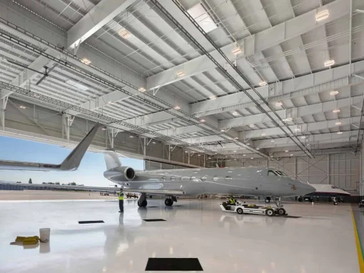
- In buildings having high ceilings, vertical delivery unit heaters equipped with the correct air-distribution devices are recommended to produce comfort in central areas of the space to be heated. Horizontal delivery units are generally used to heat the peripheral areas of the same building.
- Horizontal delivery type units should be arranged so they do not blow directly at occupants. Their air streams should be directed down aisles, into open spaces on the floor, or along exterior walls of the building.
- When only vertical delivery units are used, they should be located so that exposed walls are blanketed by their warm air streams.
10.Several unit heaters may be operated by a single thermostat. In large open spaces where similar activities are carried on, zone heating will improve comfort and generally reduce fuel costs. Unit heaters may also be controlled individually, either manually or by a thermostat.
Location Precautions
- Do not install gas or oil-fired units in potentially explosive or flammable atmospheres laden with grain dust, sawdust, or similar air-borne materials. In such applications a blower type heater is recommended in a separate room with ducting to the dust-laden room.
- Consult piping, electrical, and venting instructions in unit installation manual before installation.
- Do not locate ANY gas or oil-fired unit in areas where chlorinated, halogenated or acid vapors are present in the atmosphere.
- Unit heaters installed in an occupied zone (less than 7 feet above the floor level) must have finger-proof guards for all moving parts (fans, belts, sheaves, etc.). High temperature surfaces, such as flue pipes, must be installed or protected by guards to prevent body contact.
- Installation of unit heaters in high humidity or salt water atmospheres will cause accelerated corrosion resulting in a reduction of the normal life span of the units.